
Choosing fiber optic equipment for telecommunications FTTH builds
Key Takeaways
- Australian Energy Minister Seeks Mandatory Energy Contracts for Data CentresDr. Elena Volt
- Can a renewable energy planning platform estimate solar yield?Dr. Aris Sun
- Portugal Mandates Grid-Forming Capability for Large Storage, Launches 1 GW TenderDr. Elena Volt
- Can distributed energy systems keep commercial buildings powered during outages?Dr. Elena Volt
- China Sets Wind Power Capacity Credit Target of Around 11% by 2030Marcus Wind
- How to verify a solar water pumping system exporter's flow ratingsDr. Aris Sun
- IRENA Warns Global Clean Energy Additions Could Fall in 2026 as Grid Constraints BiteDr. Elena Volt
- What tests should a three-phase hybrid solar inverter factory run?Dr. Aris Sun
Industry Overview
Our mission is to safeguard the future of global renewable energy development through verifiable data, interdisciplinary academic scrutiny, and unwavering industry integrity.
Choosing Fiber Optic Equipment for Telecommunications FTTH Builds
Selecting fiber optic equipment for telecommunications is not a matter of filling a bill of materials with familiar part numbers. In an FTTH build, the OLT, optical splitters, feeder and distribution cables, closures, distribution frames, connectors, and test instruments operate as one physical system. A weak choice at any point can show up later as slow activation, difficult fault isolation, high truck-roll volume, or an upgrade that requires rebuilding assets that should have lasted decades.
For project leaders, the practical question is rarely “Which component is best?” It is “Which equipment set gives this network the required service level, can be installed reliably by available crews, and leaves a realistic path for growth?” That distinction matters. An urban brownfield project with crowded ducts is not specified in the same way as a greenfield residential development, a rural cluster with long feeder distances, or a mixed-use district that may later host edge computing and distributed energy controls.
This is also becoming relevant beyond conventional broadband planning. Renewable plants, battery energy storage systems, substations, and virtual power plant platforms depend on secure, resilient communications. Organizations evaluating assets across solar, wind, smart distribution, and Energy Internet applications increasingly look at fiber infrastructure as a shared operational layer. The same discipline used to benchmark grid hardware against applicable IEC, IEEE, or UL requirements should be applied to telecom equipment: verify the actual interface, environmental rating, test evidence, and lifecycle support rather than relying on a headline specification.
Start with the network architecture, not the equipment catalogue
An FTTH equipment decision should begin with a design basis that is specific enough to rule things out. Define the service mix, expected take-up pattern, geographic footprint, available duct or pole routes, central-office constraints, and desired expansion horizon. Then decide whether the access architecture is based on GPON, XGS-PON, or another approach permitted by the operator’s service strategy. Equipment compatibility must be assessed at the system level, including the optical line terminal (OLT), optical network terminals (ONTs), management platform, and the passive optical network between them.
It is tempting to standardize on the highest-capacity platform available. That can be sensible where demand for multi-gigabit access is immediate or where cabinet space is scarce. But an expensive OLT platform does not rescue a poorly planned outside plant. In many projects, duct capacity, splice accessibility, optical loss discipline, and the ability to add distribution fibers later will have more influence on lifecycle cost than the initial port speed.
A useful early exercise is to draw the full route from aggregation point to subscriber premises and mark every transition: rack to feeder cable, feeder to splitter, splitter to distribution cable, distribution to drop, and drop to terminal equipment. Each transition is a possible source of loss, contamination, documentation gaps, or future access difficulty. If the team cannot explain how a technician will reach and test a point five years after handover, the design is not complete.
The optical budget is where optimistic designs are exposed
The optical budget should drive passive component selection. It accounts for fiber attenuation over route length, splitter insertion loss, splice loss, connector loss, engineering margin, and any additional allowances required by the chosen technology and operating conditions. The exact acceptable limits depend on the selected PON standard, optics class, and supplier documentation, so they should not be assumed from a generic template.
Split ratio is often the central trade-off. Higher splitting can reduce the amount of active equipment and feeder fiber required per subscriber, but it consumes more optical budget and can narrow operational margin. A high split ratio may look efficient on a coverage map while becoming awkward in a long-reach area, especially where route changes, extra joints, or remedial work add loss after commissioning. Conversely, a lower split ratio can provide a more forgiving network, but it may demand more OLT ports, fibers, and space. There is no universally “correct” ratio; it needs to fit route length, take-up assumptions, capacity targets, and the operator’s tolerance for constrained margins.
Do not accept a passive design merely because the calculated result is just inside the limit. Field conditions are less tidy than drawings. Connector end-face contamination, unrecorded repairs, sharp handling during installation, and deviations in civil works all have a way of consuming the margin that was treated as optional on paper.
Choose OLTs and ONTs as an operating platform
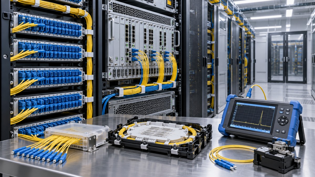
When comparing active fiber optic equipment for telecommunications, capacity is only one part of the decision. Review port density, uplink options, redundancy design, power and cooling requirements, rack depth, software licensing terms, alarm handling, remote provisioning, and interoperability commitments. A chassis that looks economical at the purchase stage can become expensive if routine subscriber activation requires manual intervention or if a software feature needed for service assurance is licensed separately.
ONT selection deserves similar attention. The device at the premises affects installation time and the customer’s perception of service quality. Consider Wi-Fi requirements where relevant, Ethernet port configuration, voice support if required, power supply approach, mounting options, local temperature conditions, and remote diagnostics. Avoid treating all ONTs as interchangeable simply because they support the same nominal PON technology. Vendor interoperability can vary in areas such as provisioning behavior, firmware management, multicast handling, and fault reporting. A lab validation using the intended OLT software release and ONT firmware is a better gate than an assurance made during a commercial meeting.
For critical communications supporting distributed generation, grid monitoring, or utility field operations, operational separation may also be needed. Consumer FTTH traffic and operational technology traffic should not be assumed to have identical resilience, security, or restoration requirements. The access layer can share physical corridors in some designs, but service segregation and failure consequences need deliberate review.
Passive infrastructure: buy for installation reality
Passive components are frequently described as commodities until a deployment team has to work with them in rain, dust, tight chambers, or a crowded riser. Cable construction should match the route and installation method: duct pulling, blowing, direct burial, aerial installation, internal risers, and short drop runs impose different mechanical and environmental demands. Check bend performance, tensile limits, cable diameter, sheath type, water-blocking design where relevant, and compatibility with planned installation equipment. A cable that meets optical requirements but cannot be installed consistently through the actual duct network is not the low-cost option.
Optical distribution frames, fiber distribution hubs, terminals, and closures should be assessed for tray capacity, splice management, labeling visibility, cable entry sealing, grounding provisions where applicable, and room for future work. Project teams often underestimate the cost of revisiting a closure that was technically compliant but difficult to reopen, identify, and reseal. The closure should support the splice count and cable configuration expected at maturity, not only at first activation.
Connector strategy also deserves a clear rulebook. Factory-terminated assemblies can reduce field time and variability in suitable locations, while fusion splicing may provide greater flexibility for complex routes and repairs. Either approach can work. Problems arise when a project mixes connector types, polish styles, cleaning practices, and labeling conventions without a controlled standard. Connector inspection and cleaning are basic disciplines, yet they remain a common source of avoidable commissioning faults.
Testing equipment is part of the network, not a commissioning afterthought
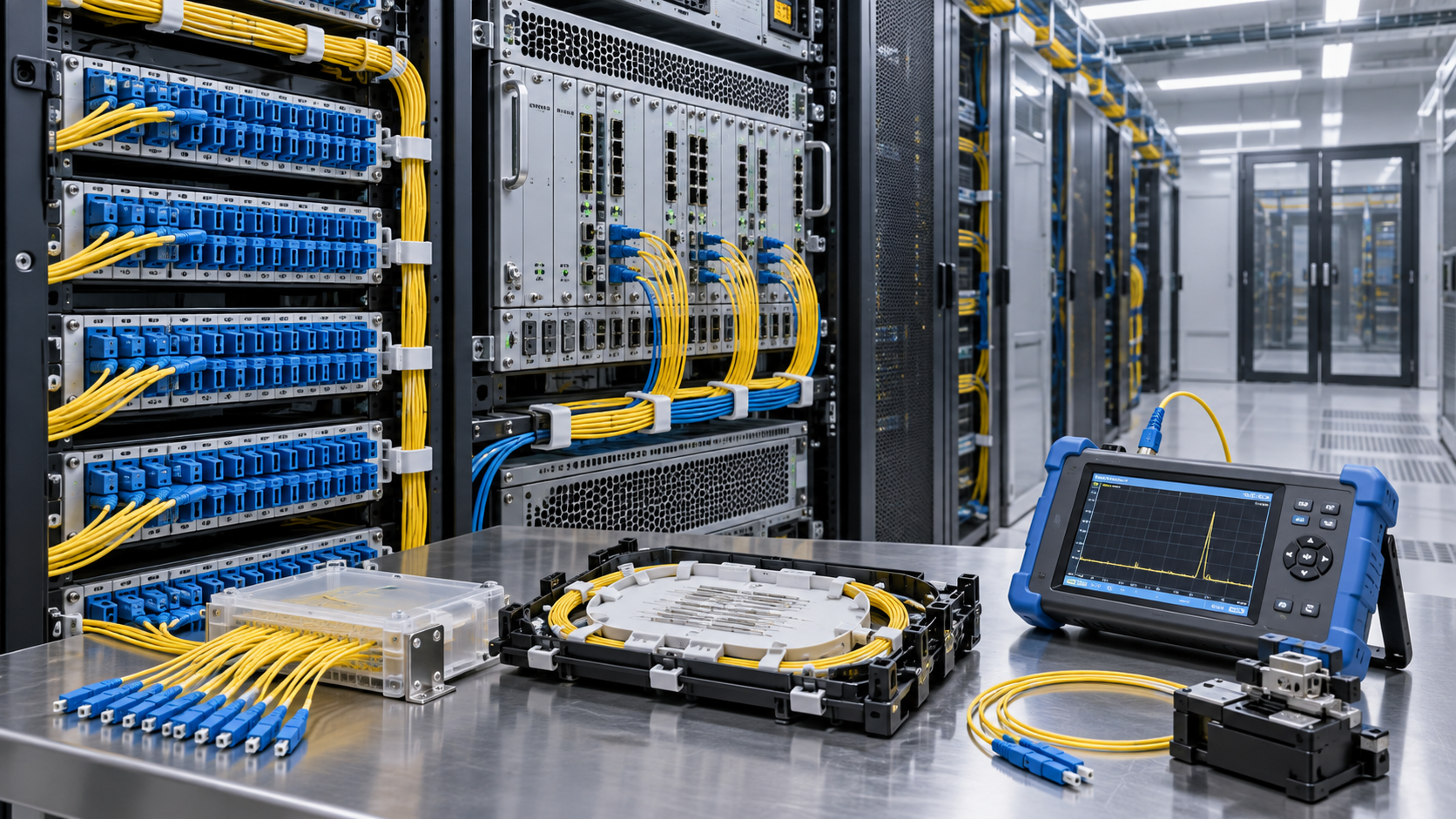
A project without a consistent test strategy cannot prove what it has built. Typical toolsets may include optical power meters, light sources, visual fault locators, connector inspection scopes, and OTDRs, but purchasing instruments alone is not enough. The team needs agreed test procedures, calibrated equipment, trained users, clear pass/fail criteria, and a record structure that ties results to cable IDs, ports, locations, and dates.
OTDR traces are particularly valuable for baseline documentation and fault investigation, yet they can be misread. Dead zones, launch conditions, event interpretation, and the direction of testing all affect what the trace appears to show. For acceptance, specify who reviews exceptions and how retesting is handled. An installer’s “pass” result has limited value if the asset owner cannot locate the relevant trace after a later outage.
For energy-linked infrastructure, documentation quality takes on extra weight. Fiber routes may cross substations, solar sites, wind farm collection networks, or municipal rights-of-way. The communication link may be physically simple, but its failure can complicate remote monitoring, dispatch visibility, or field coordination. Asset registers should therefore connect fiber records with the operational systems that depend on them.
Procurement decisions that protect the schedule
The lowest unit price can hide the largest schedule risk. Before award, confirm manufacturing lead times, approved alternates, country-of-origin constraints where applicable, warranty process, spare-part availability, packaging standards, and the supplier’s ability to provide consistent batches. This is especially important for items such as splitters, closures, pre-terminated drops, and ONTs, where a late substitution can force changes in installation practice or documentation.
A practical procurement package separates “approved equivalent” from “similar-looking substitute.” Equivalency should cover optical characteristics, mechanical interfaces, environmental suitability, compliance documentation requested by the project, and compatibility with existing accessories. It should also require a technical review before field delivery. Uncontrolled substitutions are a familiar cause of mismatched adapters, overloaded splice trays, and unexpected losses.
Where projects sit alongside smart-grid investment, procurement teams can gain value by aligning asset data requirements across telecom and energy packages. The goal is not to force every product into one specification. It is to ensure that serial records, location data, test evidence, and maintenance responsibilities can be understood across the organizations that manage communications and power assets.
A disciplined selection path
The strongest FTTH selections usually follow a simple sequence: lock the service and topology assumptions; calculate and challenge the optical budget; validate active-equipment interoperability; inspect passive components for the actual installation environment; define testing and acceptance before construction; then compare suppliers on delivered lifecycle risk rather than price alone. The sequence sounds ordinary, but skipping any part tends to transfer uncertainty to construction or operations, where it costs more to resolve.
For a network intended to serve growing digital and energy-connected communities, leave room where it is cheap to leave room: spare fibers in strategic routes, accessible closure capacity, sensible rack allowances, and documentation that a new maintenance team can use. That is usually a better investment than buying excess active capacity everywhere. The right fiber optic equipment for telecommunications is the equipment that fits the network’s real constraints, can be maintained without guesswork, and does not turn the next expansion into a recovery project.
Deep Dive
Related Intelligence
- Can a renewable energy planning platform estimate solar yield?Author :

- How to verify a solar water pumping system exporter's flow ratingsAuthor :

- Which module suppliers are winning floating solar project contracts?Author :

- What certifications should a CdTe thin-film solar panel OEM provide?Author :