How ambient temperature affects solar inverter efficiency
Key Takeaways
- Australian Energy Minister Seeks Mandatory Energy Contracts for Data CentresDr. Elena Volt
- Can a renewable energy planning platform estimate solar yield?Dr. Aris Sun
- Portugal Mandates Grid-Forming Capability for Large Storage, Launches 1 GW TenderDr. Elena Volt
- Can distributed energy systems keep commercial buildings powered during outages?Dr. Elena Volt
- China Sets Wind Power Capacity Credit Target of Around 11% by 2030Marcus Wind
- How to verify a solar water pumping system exporter's flow ratingsDr. Aris Sun
- IRENA Warns Global Clean Energy Additions Could Fall in 2026 as Grid Constraints BiteDr. Elena Volt
- What tests should a three-phase hybrid solar inverter factory run?Dr. Aris Sun
Industry Overview
Our mission is to safeguard the future of global renewable energy development through verifiable data, interdisciplinary academic scrutiny, and unwavering industry integrity.
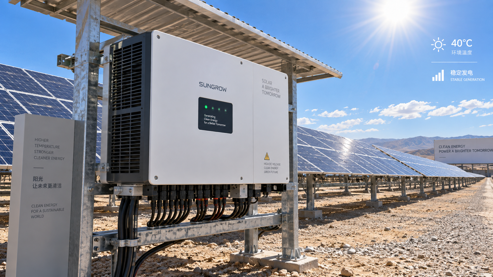
Ambient temperature affects solar inverter efficiency in two connected ways: it changes the inverter’s instantaneous conversion losses, and it can force the unit to reduce output when internal components approach their thermal limits. The first effect is usually gradual. The second can be abrupt, especially in poorly ventilated equipment rooms, rooftop installations, desert sites, or dense inverter blocks exposed to afternoon heat.
For technical evaluation, the important question is not whether an inverter has a high published peak efficiency. It is whether it can sustain the required AC output, grid-support functions, and expected service life at the temperatures the installation will actually experience. A datasheet value measured under controlled conditions is useful, but it does not describe the full thermal operating envelope.
Why higher ambient temperature reduces inverter performance
A solar inverter converts variable DC power from PV strings into grid-compatible AC power. During this process, semiconductors, magnetic components, capacitors, busbars, and control electronics generate heat. The cooling system must transfer that heat from internal components to the surrounding air or, in some designs, to a liquid-cooling circuit.
When ambient temperature rises, the temperature difference between internal components and the outside environment becomes smaller. Heat removal becomes less effective, so junction temperatures in power devices and temperatures in capacitors, inductors, and terminals rise. Higher component temperatures increase electrical resistance and switching-related losses. The inverter may therefore consume slightly more of the incoming DC energy as heat instead of delivering it as AC power.
At moderate temperatures, this loss change may be limited. The more consequential issue begins when internal temperature reaches a control threshold. The inverter’s thermal management system may then reduce current, limit active power, restrict reactive power capability, or temporarily disconnect to protect the hardware. This response is commonly called thermal derating.
Derating is a protective function, not necessarily a design defect. However, frequent or prolonged derating during high-irradiance hours can reduce annual energy yield materially, because it occurs when the PV array is most capable of producing power. It can also complicate compliance with grid-code requirements if the plant must provide reactive power, voltage support, or active-power control while the inverter is thermally constrained.
Ambient temperature is not the same as inverter temperature
A frequent assessment error is to use the weather-station air temperature as the inverter’s operating temperature. The inverter experiences a local microclimate, and that microclimate can be substantially harsher than the site-level meteorological record.
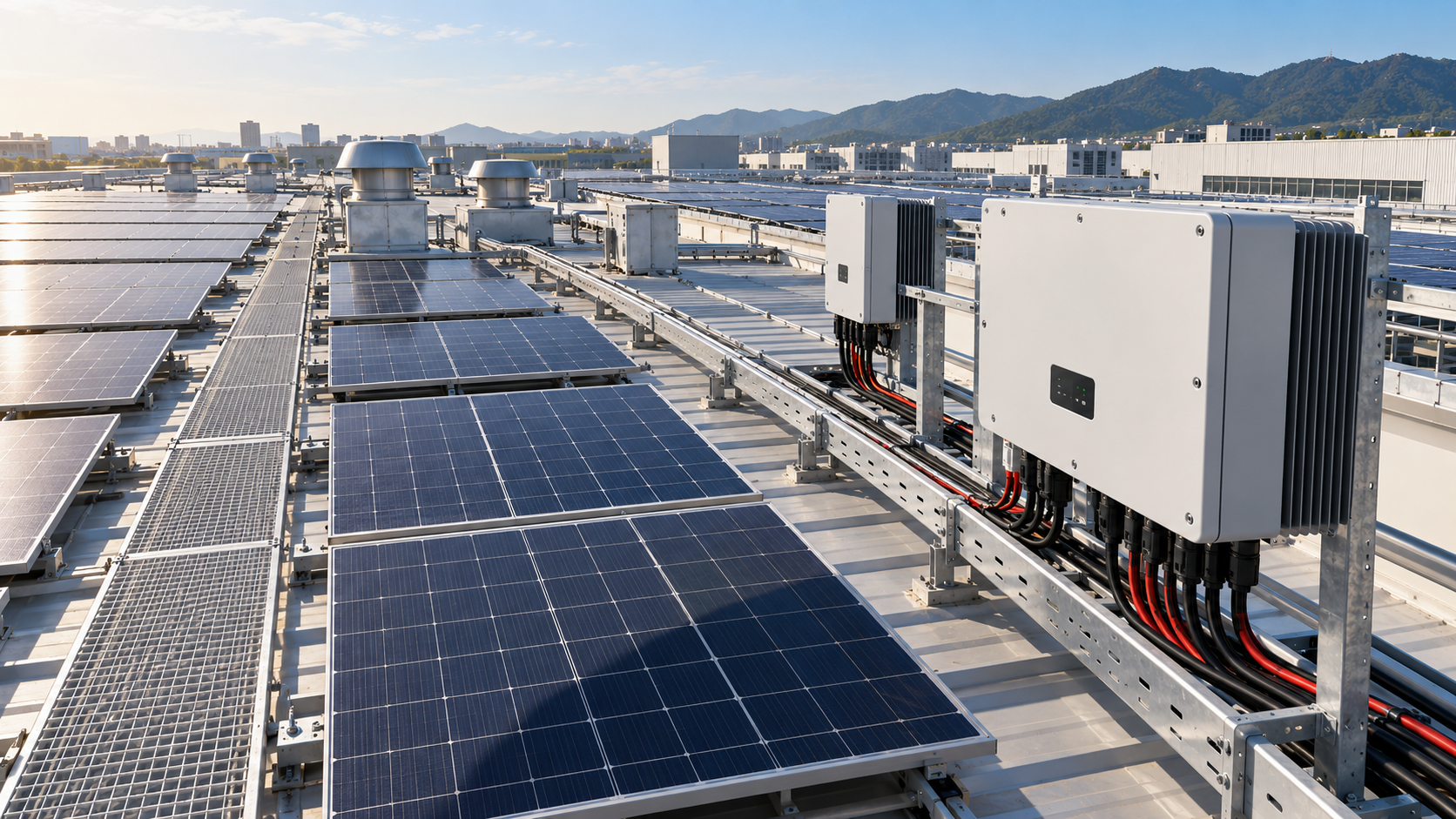
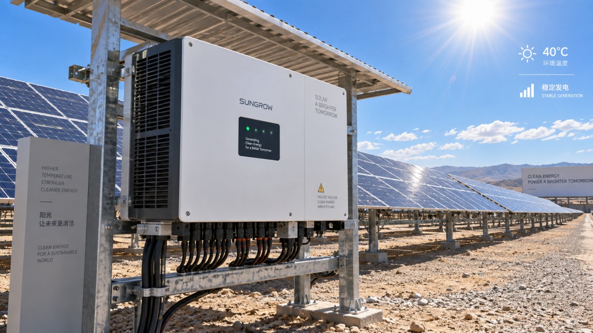
Direct sunlight on an enclosure, heat reflected from a roof membrane or concrete surface, recirculating exhaust air, blocked ventilation paths, dust accumulation, and nearby transformers can all raise the temperature around the inverter. An inverter mounted in a shaded, open-sided area may run very differently from the same model mounted on a south-facing wall or inside a compact electrical container.
PV DC loading matters as well. At a given ambient temperature, an inverter operating near its maximum DC-to-AC conversion duty generates more internal heat than one operating at partial load. The risk is therefore highest when high irradiance, elevated ambient temperature, and high DC input coincide. Energy models that treat these variables independently can understate clipping and temperature-related output restriction.
Reading datasheets without overestimating thermal capability
Published efficiency figures are commonly presented as peak efficiency and weighted efficiency. Both are valuable for comparing conversion performance across operating points, but neither alone answers how the inverter performs on a hot site.
The most useful thermal document is a derating curve or an equivalent full-power operating specification. It should show how maximum AC power changes as ambient temperature rises, ideally with the relevant voltage and installation conditions stated. A broad operating-temperature range should never be read as a full-load temperature range. An inverter may continue operating at a high ambient temperature while delivering less than nameplate power.
Technical evaluators should also separate inverter heat limits from AC-side grid limits. High ambient temperature can coincide with elevated transformer temperature, cable temperature, or switchgear temperature. A project may avoid inverter derating yet still face export restriction elsewhere in the power block.
Hot-climate evaluation: focus on the combined thermal duty
In hot regions, product selection should begin with the expected worst operating window rather than the annual average temperature. The relevant condition is often a period of strong irradiance, low wind, high local air temperature, and sustained generation near the inverter’s rated capacity.
Fan-cooled inverters can reject heat effectively when airflow is clean and unrestricted, but their performance depends on fan health, filter maintenance, and adequate clearance. Dust loading is not only a maintenance issue: it can reduce heat transfer and shift the operating point toward derating. In corrosive or sandy environments, enclosure design and maintenance access deserve the same attention as nominal efficiency.
Liquid-cooled designs can offer a more controlled heat-rejection path for high-density applications, but they introduce a different set of checks. Evaluators need to understand coolant-loop redundancy, heat-exchanger location, pump monitoring, leak detection strategy, and what occurs if the cooling system loses capacity. The appropriate choice depends on site density, operating environment, service model, and the consequences of output restriction during peak periods.
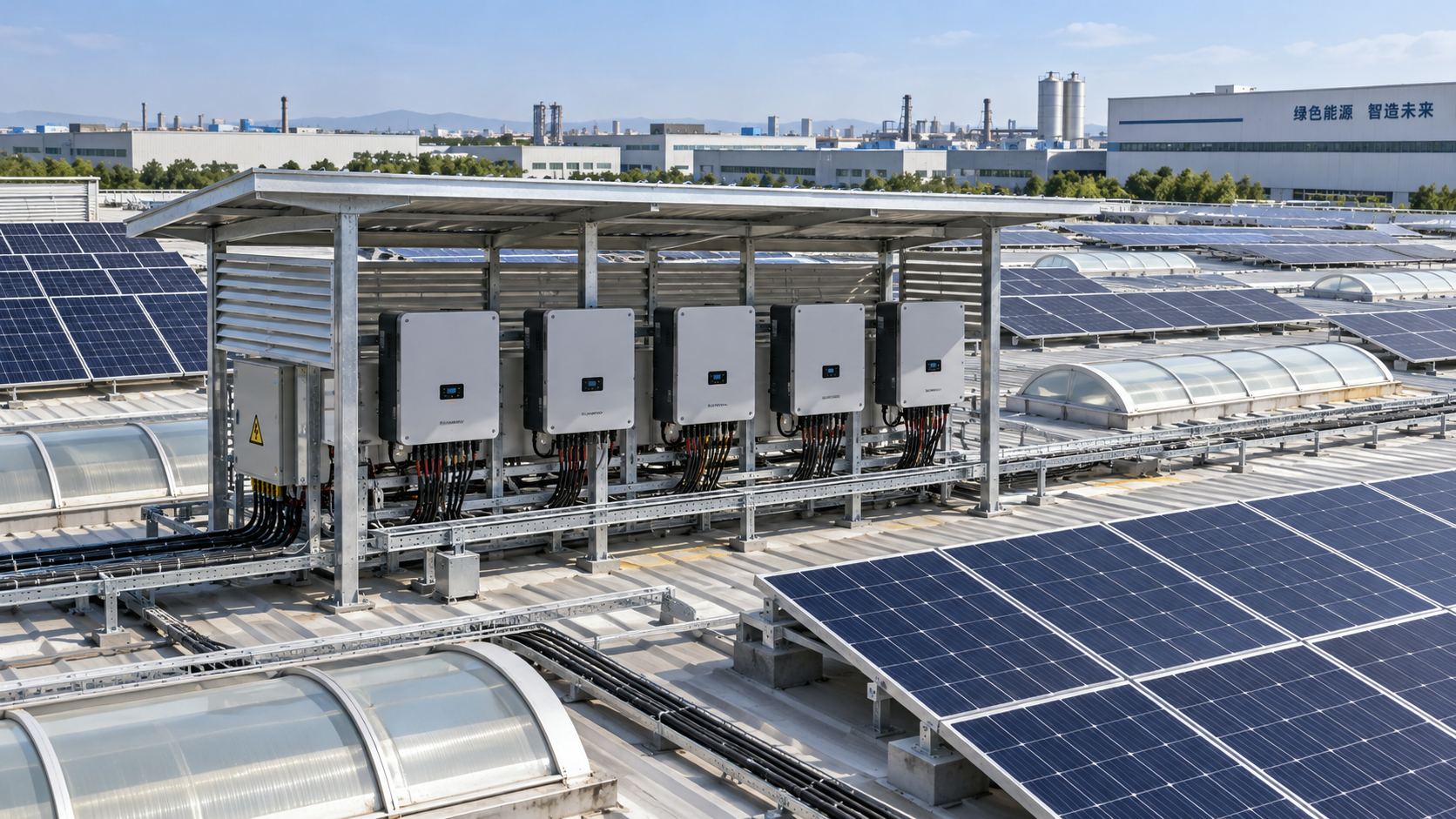
Enclosure placement is often a lower-cost thermal improvement than changing inverter architecture. Shade can reduce solar heat gain, but it must not block airflow. Equipment spacing should prevent one unit’s discharge air from becoming another unit’s intake air. In containerized systems, the thermal design must be assessed as a complete package: inverter losses, transformer losses, ventilation route, louvers, controls, and maintenance state all interact.
Cold conditions can also change efficiency and operating behavior
Lower ambient temperature generally helps heat dissipation and can reduce internal thermal stress while the inverter is operating. That does not mean cold sites are automatically easier. PV module voltage rises as module temperature falls, so cold, bright conditions can push string voltage toward the inverter’s maximum DC voltage limit. This is a DC design issue, but it must be reviewed alongside inverter selection.
Cold starts, condensation, frost, and repeated temperature cycling create different risks. A sealed outdoor inverter may avoid direct water ingress yet still experience internal moisture if installation practices, cable entry, drainage, or enclosure ventilation are inadequate. Rapid thermal cycling can also place long-term stress on solder joints, connectors, and capacitors.
For cold-climate projects, do not trade away DC voltage margin simply because thermal derating is unlikely. A system that performs well in summer may reach an unacceptable DC voltage under the lowest expected module temperature. The string design, inverter DC limit, maximum power point tracking range, and startup behavior must be checked together.
Temperature also affects lifetime, not only daily yield
Thermal stress is cumulative. Repeated high internal temperatures can accelerate aging in temperature-sensitive components, particularly capacitors and semiconductor assemblies. Frequent cycling between cool nights and hot midday operation adds mechanical stress through expansion and contraction of materials with different thermal properties.
This does not mean every hot project requires an oversized inverter. Oversizing without a yield and grid-control rationale can add cost and may shift operation away from the most favorable loading range. The more defensible approach is to compare alternatives using site-specific weather data, PV array configuration, expected DC loading, installed microclimate, and required grid services.
Where a plant is expected to operate near capacity for extended hot periods, thermal headroom can be more valuable than a marginal difference in quoted peak efficiency. Where generation is rarely near rated output, the same premium may not deliver proportional value. The decision should follow the operating profile rather than a generic climate label.
A practical thermal review for inverter selection
Before finalizing a commercial or utility-scale inverter, review the installation as a thermal system rather than a standalone device:
- Map the expected high-temperature, high-irradiance operating condition and compare it with the inverter’s full-power and derating specifications.
- Model DC voltage at low module temperature and verify adequate margin to the inverter’s maximum DC voltage.
- Define the real mounting condition: outdoor wall, ground mount, rooftop, inverter station, or container.
- Check clearances, solar exposure, airflow direction, exhaust recirculation risk, and heat sources from adjacent equipment.
- Assess whether reactive-power obligations or voltage-support modes reduce available thermal headroom at peak active power.
- Include filter cleaning, fan inspection, cooling-loop monitoring, and temperature-alarm response in the operating plan.
- Use monitoring data that distinguishes ambient temperature, enclosure temperature, internal temperature alarms, and derating events.
The last point is particularly useful after commissioning. A lower-than-expected performance ratio may be attributed to module temperature, soiling, clipping, or grid curtailment when the inverter is actually entering a thermal limit. Event logs and temperature channels allow operators to distinguish these causes and correct the right problem.
Do not use nominal efficiency as a site-performance proxy
The highest stated conversion efficiency is not automatically the best choice for a hot installation. A technically sound comparison considers conversion efficiency, thermal derating behavior, cooling architecture, local installation conditions, maintenance capability, and grid-support duty as one decision set.
For organizations benchmarking PV hardware and grid-connected assets, this is where structured technical review adds value. G-REI’s broader focus on PV equipment, smart power distribution, and grid-stability requirements reflects the practical reality that inverter selection cannot be isolated from the surrounding power block and operating controls.
The first document to request is not another headline efficiency figure. It is the evidence showing what output the inverter can sustain at the project’s likely temperature, voltage, load, and installation conditions. That is the information most likely to protect modeled yield, operational availability, and long-term asset performance.
Deep Dive
Related Intelligence
- What tests should a three-phase hybrid solar inverter factory run?Author :

- How many MPPTs does a commercial rooftop string inverter need?Author :

- How to assess quality control during an inverter factory auditAuthor :

- How Do You Choose String Inverters for a Factory Solar PV System?Author :