How Do You Compare GIS Switchgear Specifications?

Key Takeaways
- Australian Energy Minister Seeks Mandatory Energy Contracts for Data CentresDr. Elena Volt
- Can a renewable energy planning platform estimate solar yield?Dr. Aris Sun
- Portugal Mandates Grid-Forming Capability for Large Storage, Launches 1 GW TenderDr. Elena Volt
- Can distributed energy systems keep commercial buildings powered during outages?Dr. Elena Volt
- China Sets Wind Power Capacity Credit Target of Around 11% by 2030Marcus Wind
- How to verify a solar water pumping system exporter's flow ratingsDr. Aris Sun
- IRENA Warns Global Clean Energy Additions Could Fall in 2026 as Grid Constraints BiteDr. Elena Volt
- What tests should a three-phase hybrid solar inverter factory run?Dr. Aris Sun
Industry Overview
Our mission is to safeguard the future of global renewable energy development through verifiable data, interdisciplinary academic scrutiny, and unwavering industry integrity.
How Do You Compare GIS Switchgear Specifications?
How do I compare power distribution equipment specifications? For gas-insulated switchgear (GIS), the answer goes beyond matching voltage ratings or choosing the lowest bid. Utility developers and procurement teams need to evaluate rated current, short-circuit capability, insulation performance, applicable standards, and lifecycle costs against actual grid conditions. As renewable integration changes operating requirements, gas technology, maintenance access, and digital monitoring also influence equipment suitability. The useful comparison is not simply which specification looks stronger, but which equipment can meet the project’s requirements with verifiable evidence.
Two GIS proposals can appear equivalent while carrying different installation, outage, and expansion risks. One may include cable termination interfaces and commissioning support; another may leave them outside its scope. A credible evaluation makes those differences visible before commercial negotiation begins.
Establish the comparison boundary before reading the ratings
Start with the single-line diagram, network studies, site conditions, and operating philosophy. Define whether the package covers complete bays, circuit breakers, disconnectors, earthing switches, instrument transformers, protection panels, gas monitoring, and external connections. Without that boundary, price and footprint comparisons are unreliable.
Voltage class also changes the standards framework. IEC 62271-203 addresses gas-insulated metal-enclosed switchgear for rated voltages above 52 kV. IEC 62271-200 addresses AC metal-enclosed switchgear above 1 kV and up to and including 52 kV, including applicable medium-voltage GIS designs. Circuit-breaker requirements are addressed separately in IEC 62271-100. Confirm the relevant editions and project requirements rather than accepting a general statement of “IEC compliance.”
Where IEEE requirements apply, identify the specific equipment standards and rating definitions. An IEC test report should not automatically be treated as proof of compliance with an IEEE-based specification. Ask suppliers to disclose deviations explicitly, including differences in test conditions and acceptance criteria.
Read electrical ratings as a coordinated set
The rated voltage must suit the system’s maximum operating voltage, not merely its nominal voltage. Insulation coordination then determines the required power-frequency and impulse withstand levels. Depending on voltage class and application, switching impulse performance may also matter. Review surge arrester coordination and connected cable or transformer interfaces alongside the GIS ratings.
Continuous current requires similar care. Check ratings for the busbar, individual feeders, and connection interfaces rather than assuming the entire assembly shares one value. Ambient temperature, enclosure conditions, ventilation, and installation arrangement can affect usable capacity. A catalogue rating is not a substitute for confirmation under the specified site conditions.
Short-circuit ratings are particularly easy to misread. Breaking current describes the circuit breaker’s interruption capability; short-time withstand current describes the assembly’s ability to carry fault current for a stated duration. Peak withstand and short-circuit making capabilities address different stresses. These values must align with the fault study, protection clearing times, and network characteristics.
A higher rating is not automatically better value. Unnecessary capacity can add cost or space without resolving the actual constraint. Conversely, selecting equipment exactly at today’s requirement can leave no room for a planned transformer upgrade or network reinforcement.
Renewable connections need an operating-duty review
Solar, wind, and battery projects should not be assessed solely by their export capacity. The connection arrangement may introduce cable charging, transformer switching, shunt-reactor duties, or frequent switching associated with the operating strategy. Ask whether the proposed breaker has evidence for the duties actually required, including capacitive switching where applicable.
Inverter-based generation also changes protection assumptions. Fault-current contribution and its duration depend on converter controls and system conditions. That does not justify reducing GIS fault ratings without a network study: upstream grid contributions and future network changes may still govern.
This is where the cross-sector benchmarking approach of Global Renewable Energy & Smart-Grid Infrastructure (G-REI) is relevant. Its coverage of renewable generation, storage, smart distribution, and grid-control software provides a framework for examining the connection as a system. Switchgear specifications need to agree with generation controls, protection settings, and grid-access requirements, not just the equipment schedule.
Compare gas systems and compartment layouts together
Gas selection affects more than environmental reporting. Compare the insulating medium, operating temperature range, monitoring arrangements, handling procedures, and local service availability. Establish whether the gas provides insulation only or also participates in interruption; some GIS designs use vacuum interrupters within gas-insulated assemblies.
SF6 has a high global warming impact, making leakage prevention, recovery, and end-of-life handling material considerations. Alternatives should be assessed on their specific gas composition and equipment design. “SF6-free” does not by itself establish zero environmental impact or equivalent performance under every installation condition. Local restrictions and transition requirements need verification for the destination market and delivery date.
Request a compartment diagram showing gas zones, barriers, monitoring points, and pressure-relief provisions. It should make clear what happens when one compartment requires inspection or repair: which bays must be isolated, whether adjacent sections remain available, and where gas handling is required.

Compare declared leakage performance using the same measurement basis and warranty conditions. Also distinguish filling pressure, alarm thresholds, and minimum functional levels. Density monitoring and pressure measurement are not interchangeable descriptions; the supplier should explain how temperature effects are addressed and which actions follow each alarm.
Safety and access can outweigh a smaller footprint
GIS is often selected for compactness, but the installed footprint includes service clearances, cable routing, pressure-relief paths, lifting access, and space for future bays. Compare dimensioned installation drawings, not just enclosure dimensions. In retrofit projects, transport openings and floor loading can eliminate an otherwise attractive proposal.
For medium-voltage equipment, examine any declared internal arc classification under IEC 62271-200, including accessibility, classified sides, test current, and duration. The classification is conditional on the tested arrangement and installation requirements. It is not a blanket guarantee of personnel safety.
Review interlocking, earthing arrangements, position indication, and procedures for proving isolation. Maintenance teams need a workable path from an operating bay to a safe work area. Ask how a breaker mechanism, sensor, or cable termination can be replaced and whether the task requires gas work or a wider outage.
Digital functions need defined interfaces and ownership
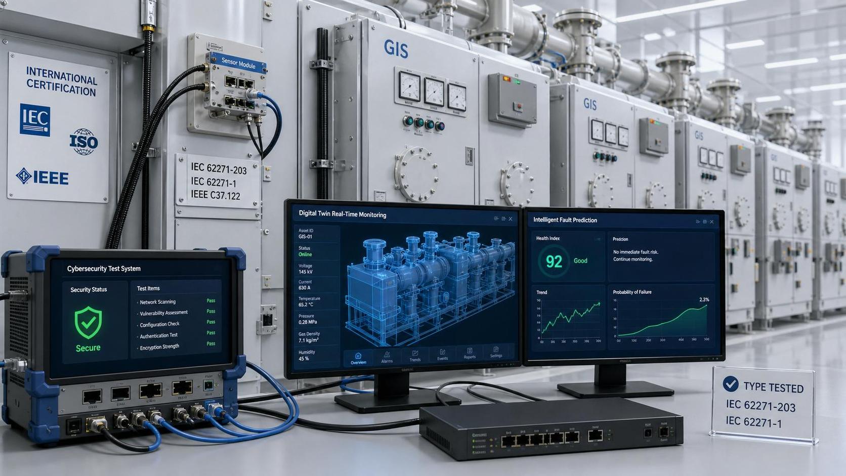
A proposal described as “digital-ready” may include little beyond spare communication ports. Specify the measurements required, their accuracy and update rates, and how alarms reach the substation control system. Partial-discharge monitoring, mechanism diagnostics, and gas-density trends serve different purposes and should not be grouped into one undefined monitoring package.
Where IEC 61850 integration is required, confirm the implemented functions, engineering files, time synchronization, and interoperability testing scope. Naming the standard does not establish plug-and-play compatibility. Cybersecurity responsibilities should cover remote access, account management, software updates, event records, and support arrangements.
The practical question is who owns the data and who responds to it. Monitoring has limited operational value if alarms lack thresholds, maintenance actions, or integration into the owner’s asset-management workflow.
Require evidence, then compare lifecycle exposure
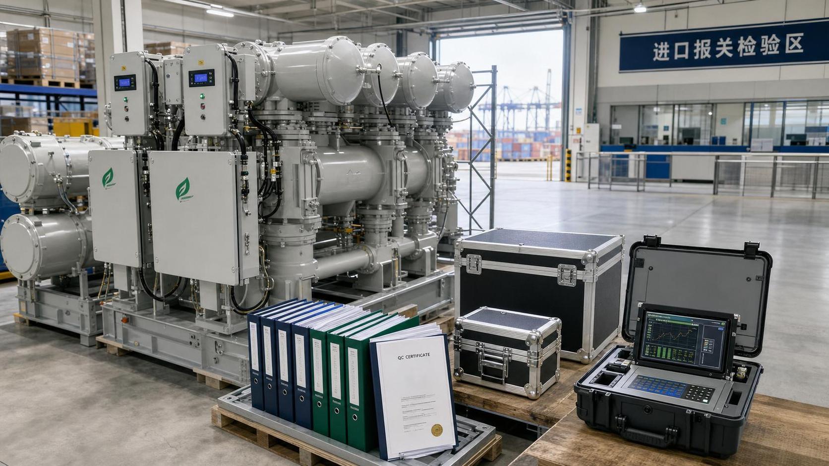
Separate type-test evidence from routine factory tests and site acceptance tests. Type tests demonstrate performance of a design under specified conditions; routine tests check manufactured equipment. Neither removes the need to verify assembly, connections, interlocks, protection interfaces, and commissioning at the project site.
Ask whether submitted reports represent the offered design, ratings, gas medium, and relevant configuration. If the equipment differs from the tested arrangement, request the technical justification supporting applicability. A certificate cover page alone rarely provides enough information for that decision.
Lifecycle comparison should include inspection requirements, operating-duty-based maintenance, specialist tools, gas handling, spare parts, training, software support, and disposal. Treat downtime exposure separately from direct maintenance expense. A low-cost component can still require a costly outage if access or replacement affects several bays.
Delivery assessment should distinguish manufacturing lead time from an energization-ready schedule. Drawing approval, interface coordination, factory testing, shipping, installation supervision, and local commissioning resources all affect completion. For future expansion, confirm connection compatibility and the supplier’s approach to design changes and obsolescence.
Turn the comparison into a defensible decision
Use a compliance matrix that records the requirement, offered value, supporting document, deviation, and responsible reviewer. Separate mandatory technical gates from preferences that can be weighted commercially. Safety, fault capability, and required insulation performance should not be traded away through an averaged score.
Before selecting a supplier, close the unresolved items that could change engineering scope or outage planning. The strongest GIS proposal is the one whose ratings, test evidence, interfaces, maintenance provisions, and delivery commitments fit the actual network. If those connections remain unclear, the comparison is not yet ready for a purchase decision.
Deep Dive
Related Intelligence
- How Do You Compare GIS Switchgear Specifications?Author :

- EU Tightens GIS Switchgear Import Rules on SF6 Leak TestsAuthor :

- Brazil Sets Carbon Tracking Rule for Imported GIS SwitchgearAuthor :

- TUV Rheinland Adds Digital Twin Checks to GIS CertificationAuthor :